Project:
Contact:
via mail ✉
Object:
Zölly Tower
Type:
appartement-tower
Location:
Zurich [satellite]
Country:
Switzerland
Architect:
Materials:
NägeleBau GmbH 🔗, Röthis (client)
Published:
BFT 01/2014
Pages:
40 - 45
Content:
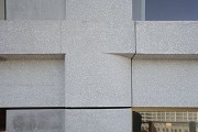
The façade of the Zölly Tower in Zurich, Switzerland, was designed with an envelope composed of precast elements to take up all loads
Precast elements for the Zölly Tower in Zurich
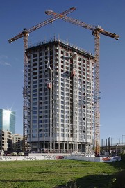
A prime residential development is currently underconstruction in the western part of Zurich, the Swiss economic hub, in the area of a former railway junction. In urban terms, the so-called ZöllyTower with its 24 stories is the center point of this project. Contrary to common practice, the architects commissioned with the detailed design exercise, the Swiss Planwerk CH GmbH based in Laufen, did not include load-bearing internal columns and a curtain façade in the design of the building. Instead, they conceived a building envelope composed of precast elements that were to absorb all loads.
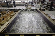
Using glass-fiber reinforced plastic for formwork fabrication
“At the very heart of the entire project was its thorough logistics planning prior to commencing construction activity,” stated Dr.-Ing. José Colan, plant manager at Nägelebau GmbH. “Although the 950 precast elements appear identical from a distance, for instance when viewed from the neighbouring Pfingstweidpark, they also include a wide variety of details. For us, the biggest issue was to manufacture the vertical pilaster strips of the building envelope, whose edges are usually rounded.” Plant manager Colan went on to explain that it was precisely this design that presented the greatest project challenges in terms of ensuring commercial viability and quality control: “Timber, as the obvious choice for the formwork, would have been subject to excessive wear (only up to 20 elements can be produced per form). In terms of the end result, steel would be the material of choice, but would have been too costly due to the large number of design variants.” The problem was solved by using forms supplied by Fibertech GmbH, a company located in Chemnitz, Germany, that produces precast element forms that consist of glass-fiber reinforced plastic (GFRP). These forms are very durable. Their facing is as smooth as that of steel forms, but they are more lightweight and less expensive compared to steel. The formwork components have a compound design: aluminum sheet serves as the carrier onto which the GFRP is sprayed. This plastic-metal compound was lined with a metal frame to incorporate it in the custom fabrication of the formwork required for each façade panel. Utmost care was also necessary at the compaction stage. Vibrating cylinders, which are otherwise commonly used for such a filigree formwork, were not an option because the precast elements were to be sandblasted in a subsequent work step to achieve a quarry stone appearance in some areas. The use of a vibrating cylinder would have led to the accumulation of lightweight concrete aggregates around the cylinder during the compaction phase whilst triggering the formation of unsightly concentric circles in the cast stone. The inevitable other option was thus to use a vibrating table, which is why the formwork arrangement had to be extremely stable.
“At the very heart of the entire project was its thorough logistics planning prior to commencing construction activity,” stated Dr.-Ing. José Colan, plant manager at Nägelebau GmbH. “Although the 950 precast elements appear identical from a distance, for instance when viewed from the neighbouring Pfingstweidpark, they also include a wide variety of details. For us, the biggest issue was to manufacture the vertical pilaster strips of the building envelope, whose edges are usually rounded.” Plant manager Colan went on to explain that it was precisely this design that presented the greatest project challenges in terms of ensuring commercial viability and quality control: “Timber, as the obvious choice for the formwork, would have been subject to excessive wear (only up to 20 elements can be produced per form). In terms of the end result, steel would be the material of choice, but would have been too costly due to the large number of design variants.” The problem was solved by using forms supplied by Fibertech GmbH, a company located in Chemnitz, Germany, that produces precast element forms that consist of glass-fiber reinforced plastic (GFRP). These forms are very durable. Their facing is as smooth as that of steel forms, but they are more lightweight and less expensive compared to steel. The formwork components have a compound design: aluminum sheet serves as the carrier onto which the GFRP is sprayed. This plastic-metal compound was lined with a metal frame to incorporate it in the custom fabrication of the formwork required for each façade panel. Utmost care was also necessary at the compaction stage. Vibrating cylinders, which are otherwise commonly used for such a filigree formwork, were not an option because the precast elements were to be sandblasted in a subsequent work step to achieve a quarry stone appearance in some areas. The use of a vibrating cylinder would have led to the accumulation of lightweight concrete aggregates around the cylinder during the compaction phase whilst triggering the formation of unsightly concentric circles in the cast stone. The inevitable other option was thus to use a vibrating table, which is why the formwork arrangement had to be extremely stable.
Precast elements form a sandwich structure
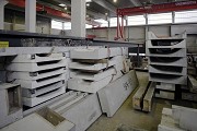
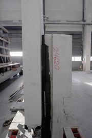
The precast elements form a sandwich structure. They include a distinctly shaped three-dimensional external leaf (facing layer) and a relatively flat internal leaf (load-bearing layer). The space between these parts is filled with a 16 to 24 cm thick foam glass insulation layer, which provides the added advantage of high geometrical accuracy and thus enabled the manufacture of precast elements with utmost precision. In the first work step, the external leaf was cast for all elements. After curing, factory staff placed the black rigid-foam material on the concrete surface. ComBar thermal anchors supplied by Schöck were embedded in this material to permanently connect the external and internal leaves whilst eliminating thermal bridges completely. About eight anchors were placed per square meter to establish a load-bearing connection between the two concrete layers. ComBar thermal anchors provide the advantage that they do not need to be linked to the reinforcement prior to concrete pouring. Instead, they can be inserted after completion of the casting process. This approach also eliminated the need for the insulation to be laid around the projecting anchors in a highly complex arrangement. In addition, it was crucial to consider the clearance of the carousel system during the planning process. Although the Röthis production line has a 1-meter clearance, things got really tight as precast elements (with an average thickness of 61 cm) were raised in several subsequent steps whilst the required rails had to be taken into account as well.
The precast elements form a sandwich structure. They include a distinctly shaped three-dimensional external leaf (facing layer) and a relatively flat internal leaf (load-bearing layer). The space between these parts is filled with a 16 to 24 cm thick foam glass insulation layer, which provides the added advantage of high geometrical accuracy and thus enabled the manufacture of precast elements with utmost precision. In the first work step, the external leaf was cast for all elements. After curing, factory staff placed the black rigid-foam material on the concrete surface. ComBar thermal anchors supplied by Schöck were embedded in this material to permanently connect the external and internal leaves whilst eliminating thermal bridges completely. About eight anchors were placed per square meter to establish a load-bearing connection between the two concrete layers. ComBar thermal anchors provide the advantage that they do not need to be linked to the reinforcement prior to concrete pouring. Instead, they can be inserted after completion of the casting process. This approach also eliminated the need for the insulation to be laid around the projecting anchors in a highly complex arrangement. In addition, it was crucial to consider the clearance of the carousel system during the planning process. Although the Röthis production line has a 1-meter clearance, things got really tight as precast elements (with an average thickness of 61 cm) were raised in several subsequent steps whilst the required rails had to be taken into account as well.
Precast elements subjected to sand blasting, cleaning and hydrophobic treatment
For the Zölly Tower, the architects specified aggregates composed of marble and bright sand. An Italian supplier, Ferrari Granulati Marmi sas based in Grezzana (Verona), was contracted with supplying this aggregate mix. Some precast element segments were sand-blasted to emphasize the materiality of the concrete stone. As construction activity progressed, the following issue arose: beginning at their connecting points, the scaffolds erected alongside the façade triggered the formation of surface rust on the precast elements that had just been delivered to the construction site. A special cleaning process proved to be the only option to remove these surface stains caused by site conditions. After their manufacture, precast elements were sand-blasted, delivered to the site and assembled. They were not treated chemically. Once the individual elements had resisted the soiling caused by nearby construction activity more or less successfully, and the scaffolds moved into their next position, the elements were cleaned and subjected to hydrophobic treatment. The cleaning and hydrophobing agents used for this purpose were supplied by BASF Construction Chemicals Europe AG.
For the Zölly Tower, the architects specified aggregates composed of marble and bright sand. An Italian supplier, Ferrari Granulati Marmi sas based in Grezzana (Verona), was contracted with supplying this aggregate mix. Some precast element segments were sand-blasted to emphasize the materiality of the concrete stone. As construction activity progressed, the following issue arose: beginning at their connecting points, the scaffolds erected alongside the façade triggered the formation of surface rust on the precast elements that had just been delivered to the construction site. A special cleaning process proved to be the only option to remove these surface stains caused by site conditions. After their manufacture, precast elements were sand-blasted, delivered to the site and assembled. They were not treated chemically. Once the individual elements had resisted the soiling caused by nearby construction activity more or less successfully, and the scaffolds moved into their next position, the elements were cleaned and subjected to hydrophobic treatment. The cleaning and hydrophobing agents used for this purpose were supplied by BASF Construction Chemicals Europe AG.
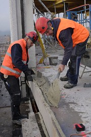
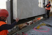
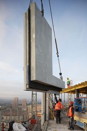
Jib cranes for precast element assembly
Using two large jib cranes, the individual precast elements were lifted from their inloader pallets on the ground and moved into their final positions. The bottom edge of the internal leaf was placed on the plain outer floor edges. By contrast, the thermal insulation and the external leaf of the individual elements proj-ected from the cast-inplace floor structure and thus provided a facing whilst creating a link to the upper precast element edge of the story underneath at the level of the bottom floor edge. The façade units were fastened by fish plates at the bottom and projecting steel bars at the top. During assembly, the elements rested on diagonal supports. Furthermore, the precast components were placed on a mortar bed that the members of the assembly team applied to the floor prior to moving the precast element into its installation position. Toward the outside, they placed a 3 cm thick strip of insulating wool in front of the mortar. Per each element, two earthlead copper wires about the thickness of a finger also protruded from the floor and were connected to the element. Workers moved the elements into their final positions in a completely manual process: while still on the hook of the crane, the elements were aligned using a large crow bar and a long spirit level. Given that Nägelebau, the precast element producer, carried out most of the shell construction work but required only a few staff members for assembly, this project example once again demonstrates how efficient precast can be.
Robert Mehl, Aachen
http://www.bft-online.info